Designed to make the extraordinary feel considered.
Not a promise of tomorrow. A transparent exploration of the systems personal VTOL will need to earn trust.
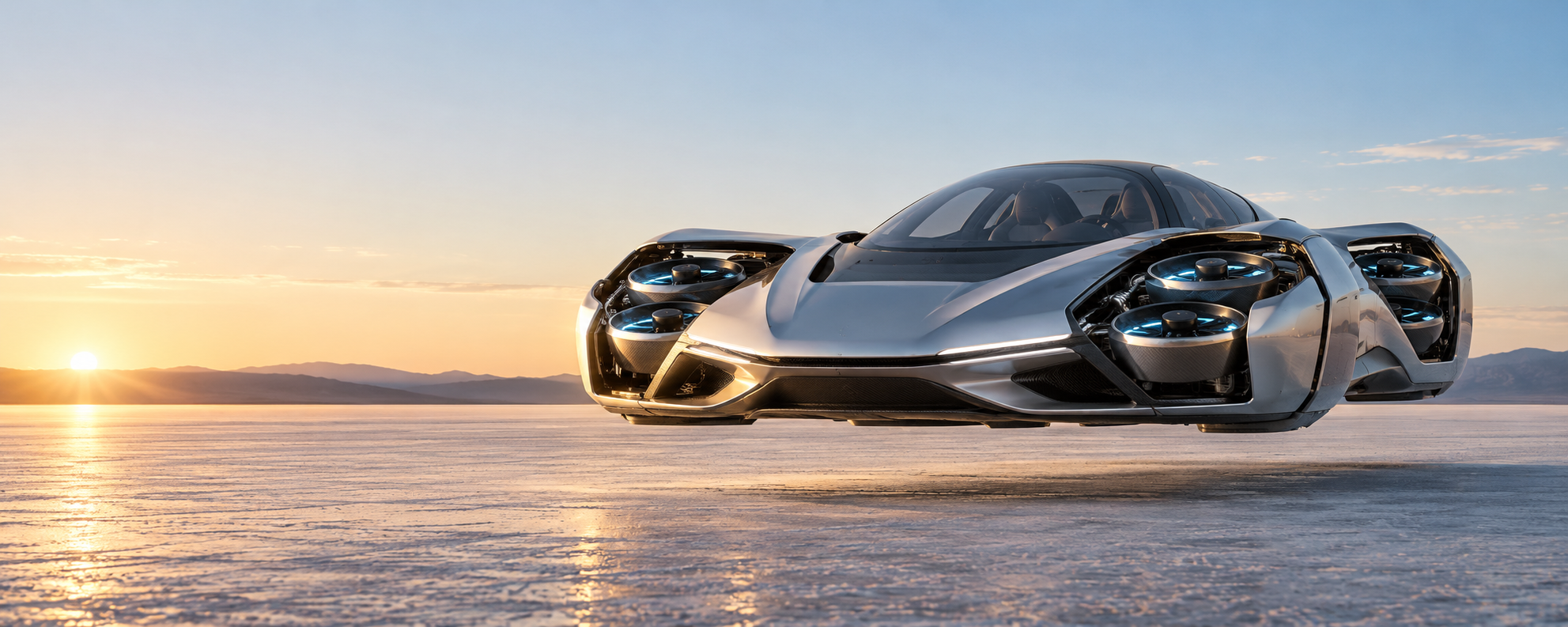
AURORA X1 explores a calmer, more realistic route to personal flight: road-ready proportions, protected ducted lift, and an electric-first power system designed for practical range.
Not a promise of tomorrow. A transparent exploration of the systems personal VTOL will need to earn trust.
Road-going length target
Independently controlled lift fans
Battery-first with generator reserve
Its compact coupe form stays familiar on the road. When cleared for flight, concealed panels open and the lift system comes alive.
The X1 concept replaces exposed propellers with compact, shrouded electric fans. That makes a lower, more car-like body possible while placing control authority close to the vehicle centre.
Every stage is visible and intentional, with no sudden jumps from a normal car to an unbelievable aircraft.
Panels closed. Road wheels engaged. The vehicle retains its compact, protected exterior.
At an approved take-off area, panels open and avionics confirm fan, battery and weather status.
Eight fans share lift demand independently for a smooth, electronically stabilised climb.
Fan thrust tilts progressively to generate forward motion, while the computer maintains a safe envelope.
The X1 uses a battery-first system for flight response and low local noise, with an onboard compact generator concept for extending range and preserving a reserve.
Every public performance figure is a concept target until it has been measured. The ledger sets a more honest standard for the work ahead.
The first investment decision is not a production vehicle. It is whether the critical assumptions can be tested safely and measured clearly.
Personal flight will only matter if it can be understood and trusted. The X1 concept uses layered independence: distributed lift, isolated energy modules and multiple flight computers. Any real development pathway would need staged testing and aviation authority engagement before crewed operation.
The X1 is a concept study. A credible program starts by proving each subsystem in controlled stages, before attempting a crewed vehicle.
Measure fan thrust, motor temperature, battery response and generator charging behaviour under load.
Validate the control software, redundancy strategy and transition logic without people aboard.
Prove integration, cooling, vibration and safe panel deployment before tethered hover trials.
Develop the evidence, operating limits and approvals needed for any later flight testing.
This is an intentionally staged program: learn with the smallest safe system first, then earn the right to build the next one.
Instrument one ducted fan, controller, battery module and cooling loop. Establish thrust, efficiency, heat, vibration and fault behaviour before selecting a production architecture.
Compare battery-only and range-extender operating modes under representative electrical loads. The generator selection remains open until its mass, noise and reliability trade-offs are measured.
Validate distributed lift control, autonomy boundaries and transition logic with no occupants aboard. This creates the first repeatable flight-test evidence package.
Prove integration on the ground before any tethered hover work. A crewed vehicle is outside the scope of the early prototype program.
For the current concept brief, research updates or a partnership conversation, send a briefing request. We will respond from the project team.
AURORA X1 is a design and research concept, not a certified aircraft, vehicle or commercial offer. Technical values shown on this site are provisional design targets and may change after analysis, supplier engagement and test evidence. Any future flight activity would require an appropriate safety case, approvals and regulatory engagement. The site does not claim that any depicted system has been built, tested, approved or made available for transport.